Use .NET IoT Libraries on Windows, Linux, and macOS computers
The .NET IoT libraries are commonly used to develop code for Raspberry Pi and other IoT devices. However, you can also use them to develop code for Windows, Linux, and macOS PCs using a USB-to-serial adapter such as the FTDI FT232H. This article shows you how to use the .NET IoT libraries to communicate with devices connected to the FT232H adapter.
Tip
This article uses an FTDI FT232H adapter, but you can use any USB-to-serial adapter that is supported by the .NET IoT libraries, such as the FT2232H, FT4232H, and FT4222. Check the list of supported device bindings for more information.
Prerequisites
Ensure you have installed the D2XX drivers for your USB-to-serial adapter, which are found on the FTDI website.
Note
Windows devices may automatically install the drivers when you plug in the adapter. Check Device Manager for a device named USB Serial Converter listed under Universal Serial Bus controllers. The device's driver provider should be FTDI.
List available devices
Before you can create a GPIO, I2C, or SPI device, you must identify the connected USB-to-serial adapter. The following code lists the connected FTDI devices:
using Iot.Device.FtCommon;

var devices = FtCommon.GetDevices();
Console.WriteLine($"{devices.Count} available device(s)");
foreach (var device in devices)
{
    Console.WriteLine($"  {device.Description}");
    Console.WriteLine($"    Flags: {device.Flags}");
    Console.WriteLine($"    Id: {device.Id}");
    Console.WriteLine($"    LocId: {device.LocId}");
    Console.WriteLine($"    Serial number: {device.SerialNumber}");
    Console.WriteLine($"    Type: {device.Type}");
}

if (devices.Count == 0)
{
    Console.WriteLine("No device connected");
    return;
}
In the preceding code, the FtCommon.GetDevices() method returns a list of all connected FTDI devices.
Use a GPIO device
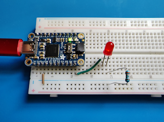
Here's a hardware implementation of the Blink an LED tutorial that uses the FTDI FT232H adapter to control an LED:
In the preceding image, the LED circuit is very similar to the original tutorial. The only difference is that the LED is connected to pin D7 on the FT232H adapter instead of pin 18 on the Raspberry Pi.
The code for the tutorial is also similar to the original tutorial:
using System.Device.Gpio;
using Iot.Device.Ft232H;
using Iot.Device.FtCommon;

Console.WriteLine("Blinking LED. Press Ctrl+C to end.");

Ft232HDevice ft232h = new Ft232HDevice(FtCommon.GetDevices()[0]);
GpioController controller = ft232h.CreateGpioController();

int pin = Ft232HDevice.GetPinNumberFromString("D7");
controller.OpenPin(pin, PinMode.Output);
bool ledOn = true;
while (true)
{
    controller.Write(pin, ledOn ? PinValue.High : PinValue.Low);
    Thread.Sleep(1000);
    ledOn = !ledOn;
}
In the preceding code:
- An instance
Ft232HDeviceis created by passing the first device ID returned byFtCommon.GetDevices()to the constructor. - An instance of
GpioControllernamed controller is created by callingCreateGpioController()on theFt232HDeviceinstance. ThisGpioControllerinstance performs the same functions as theGpioControllerinstance in the original tutorial. - The integer value of the pin is retrieved by calling
GetPinNumberFromString()on theFt232HDeviceinstance and passing in the alphanumeric pin name D7. - The rest of the code is identical to the original tutorial.
Use an I2C device
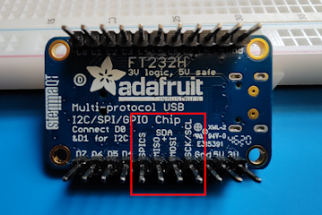
For I2C communication, the D0 and D1 pins on the FT232H adapter are used for the SDL and SCA lines, respectively. The I2C selector switch on the FT232H adapter must be set to On.
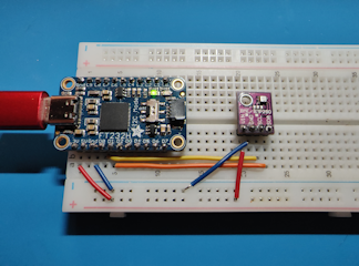
Here's a hardware implementation of the Read environmental conditions from a sensor tutorial that uses the FTDI FT232H adapter to read temperature, humidity, and barometric pressure from a BME280 sensor:
In the preceding image:
- The D0 and D1 pins on the FT232H adapter are connected to the SDL and SCA pins on the BME280 breakout board, respectively.
- The I2C selector switch on the BME280 breakout board is set to On.
using System.Device.I2c;
using Iot.Device.Bmxx80;
using Iot.Device.Bmxx80.PowerMode;
using Iot.Device.Ft232H;
using Iot.Device.FtCommon;

Ft232HDevice ft232h = new Ft232HDevice(FtCommon.GetDevices()[0]);
I2cConnectionSettings i2cSettings = new I2cConnectionSettings(0, Bme280.SecondaryI2cAddress);

using I2cDevice i2cDevice = ft232h.CreateI2cDevice(i2cSettings);
using Bme280 bme280 = new Bme280(i2cDevice);

int measurementTime = bme280.GetMeasurementDuration();

while (true)
{
    Console.Clear();

    bme280.SetPowerMode(Bmx280PowerMode.Forced);
    Thread.Sleep(measurementTime);

    bme280.TryReadTemperature(out var tempValue);
    bme280.TryReadPressure(out var preValue);
    bme280.TryReadHumidity(out var humValue);
    bme280.TryReadAltitude(out var altValue);

    Console.WriteLine($"Temperature: {tempValue.DegreesCelsius:0.#}\u00B0C");
    Console.WriteLine($"Pressure: {preValue.Hectopascals:#.##} hPa");
    Console.WriteLine($"Relative humidity: {humValue.Percent:#.##}%");
    Console.WriteLine($"Estimated altitude: {altValue.Meters:#} m");

    Thread.Sleep(1000);
}
In the preceding code:
- An instance
Ft232HDeviceis created by passing the first device ID returned byFtCommon.GetDevices()to the constructor. - An instance of
I2cDeviceis created by callingCreateI2cDevice()on theFt232HDeviceinstance. ThisI2cDeviceinstance performs the same functions as theI2cDeviceinstance in the original tutorial. - The rest of the code is identical to the original tutorial.
Use an SPI device
For SPI communication, the D0, D1, D2, and D3 pins on the FT232H adapter are used for the SCK, MOSI, MISO, and CS lines, respectively. The I2C selector switch on the FT232H adapter must be set to Off.
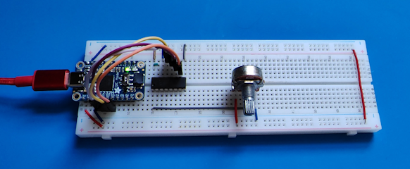
Here's a hardware implementation of the Read values from an analog-to-digital converter tutorial that uses the FTDI FT232H adapter to read values from an MCP3008 ADC:
In the preceding image:
- The D0, D1, D2, and D3 pins on the FT232H adapter are connected to the CLK, DIN, DOUT,and CS/SHDN pins on the MCP3008, respectively.
- The I2C selector switch on the MCP3008 breakout board is set to Off.
using System.Device.Gpio;
using System.Device.Spi;
using Iot.Device.Adc;
using Iot.Device.Ft232H;
using Iot.Device.FtCommon;

var devices = FtCommon.GetDevices();
var ft232h = new Ft232HDevice(devices[0]);
var hardwareSpiSettings = new SpiConnectionSettings(0, 3) { ClockFrequency = 1_000_000, DataBitLength = 8, ChipSelectLineActiveState = PinValue.Low };
using SpiDevice spi = ft232h.CreateSpiDevice(hardwareSpiSettings);
using var mcp = new Mcp3008(spi);
while (true)
{
    Console.Clear();
    double value = mcp.Read(0);
    Console.WriteLine($"{value}");
    Console.WriteLine($"{Math.Round(value/10.23, 1)}%");
    Thread.Sleep(500);
}
In the preceding code:
- An instance
Ft232HDeviceis created by passing the first device ID returned byFtCommon.GetDevices()to the constructor. - An instance of
SpiDeviceis created by callingCreateSpiDevice()on theFt232HDeviceinstance. ThisSpiDeviceinstance performs the same functions as theSpiDeviceinstance in the original tutorial. - The rest of the code is identical to the original tutorial.
Get the code
The code for this tutorial is available on GitHub.
Feedback
Coming soon: Throughout 2024 we will be phasing out GitHub Issues as the feedback mechanism for content and replacing it with a new feedback system. For more information see: https://aka.ms/ContentUserFeedback.
Submit and view feedback for


